FREQUENCYVOLTAGECONVERTER Circuit Diagram A voltage-to-frequency converter (VFC) is an oscillator whose frequency is linearly proportional to a control voltage. The VFC/counter ADC is monotonic and free of missing codes, integrates John L. Lindesmith, "Voltage-to-Digital Measuring Circuit," U.S. Patent 2,835,868, filed September 16, 1952, issued May 20, 1958. (voltage-to-frequency
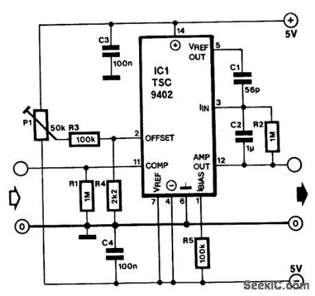
A proven way to send an analogue signal a long distance is to transport the signal as a frequency using a voltage to frequency converter (VFC), a special circuit whose output is a frequency that is proportional to its input voltage. Author's circuit of the VFC module wired on a breadboard is shown in Fig. 2. Fig. 2: Author's circuit on

2 Simple Voltage to Frequency Converter Circuits Explained Circuit Diagram
Project Build - 555 Timer Voltage to Frequency ConverterSubscribe to the channel: https://www.youtube.com/channel/UCNt-VKnOf-6-vVYqdiI_K8g?sub_confirmation=

Want to develop your own voltage to frequency converter? Yes, it's possible. And not too difficult.Watch this video to see the proof-of-concept. Plus, get to
A Basic Voltage To Frequency Converter Circuit Diagram
This type of circuit is widely used in various applications, especially in analog to digital converters and frequency modulation. The basic idea behind a VFC is to generate a frequency that is linearly proportional to the input voltage. This circuit takes 0V to 10V DC as input voltage. This circuit contains operational amplifier stage and Timer
