DIY Non Contact IR Thermometer V10 16 Steps with Pictures Circuit Diagram View the full DIY project article: https://circuitdigest.com/microcontroller-projects/contactless-smart-thermometer-using-mlx90615-ir-temperature-sensor-ardu 📱 Build a Contactless Smart Thermometer! 🔧🤖 Discover how to make a contactless smart thermometer using the MLX90615 IR temperature sensor, Arduino, and A
If your sensor is not on breakout board gonna need to pull-up the SDA and SCL pins of it, the put a capacitor between the GND and +3.3v pins. If its on breakout board then just connect the pins to the Arduino board, SDA with A5 and SCL with A4, GND to GND and +3.3 to 3.3v.
Simple Contactless Thermometer Circuit Circuit Diagram
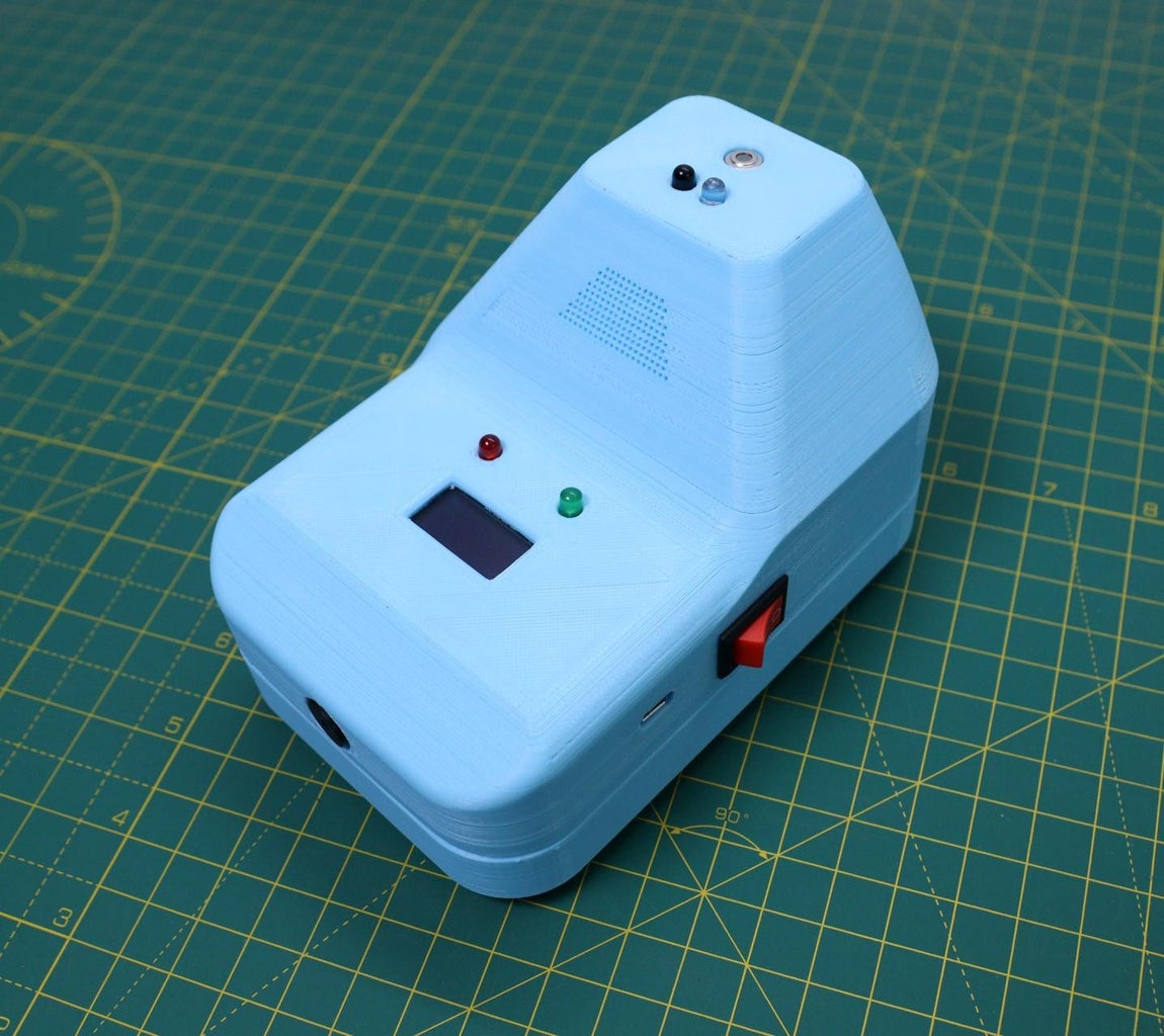
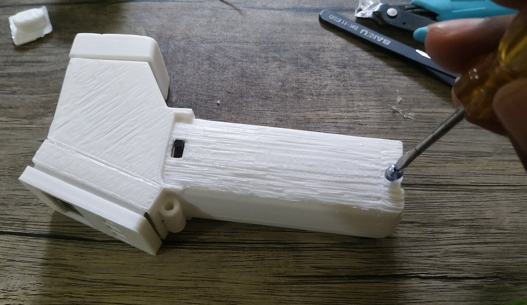
The working principle is very simple, the infrared thermometer sensor MLX90614 reads the human body temperature when the distance ( measured by IR sensor ) between the forehead and the sensor matches a set value. After making the circuit, I realized that the wiring connection is really messy. To make the wiring cleaner and simpler, I have This simple Arduino project can be used to monitor your own temperature every morning or used in public places as contact less thermometer. Contactless Thermometer. circuit diagram. circuit diagram. circuit diagram. circuit diagram. Comments. 3D Printed Enclosure for Contactless IR Thermometer. The idea of the project is to make the thermometer compact enough to mount it along with our phone. We designed a CAD model to fit all the electronics into a neat little box used paper clip to secure the device with the phone. The CAD model is shown below.
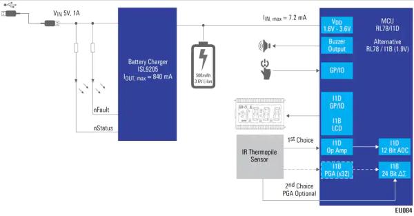
Verify temperature readings: Compare the temperature readings from the contactless thermometer with a known reference, such as a calibrated mercury thermometer or a high-quality digital thermometer. If the readings differ significantly, calibrate the MLX90614 sensor as described in the "Calibrating the Thermometer" section. In the above prototype circuit of a contactless IR thermometer circuit, we find the thermopile sensor IC MLX90247 in the bipolar mode, configured with an external op amp designed to amplify tiny electrical from the thermopile into a measurable output. A simple differential VU meter is attached across the outputs of the two op amps. As long
